Press Releases(Archive)
Report on the Investigation of the Joetsu Shinkansen Derailment
East Japan Railway Company
February 8, 2008
At 17:56 on 23 October 2004, an earthquake with a maximum intensity of 7 and a magnitude of 6.8 occurred. The epicenter was in the Chuetsu region of Niigata Prefecture, and a Joetsu Shinkansen train, Toki No. 325, derailed while running between Urasa and Nagaoka stations.
This was the first time a Shinkansen train had derailed during commercial operation since the opening of the Tokaido Shinkansen in 1964. The East Japan Railway Company established the Joetsu Shinkansen Derailment Investigative Special Committee to investigate and study the accident. The investigation was conducted in three stages - investigation of the derailment status, investigation of the derailment mechanism, and investigation of the behavior of the railcars after derailment. Company-wide efforts were made to understand the causes of the derailment and to take measures to prevent similar accidents. The results of the committee's investigation are summarized and reported here.
As a consequence of the investigation, the company was able to clarify the actual circumstances under which derailments can be caused by earthquake tremors while a train is running, and measures were put into place to prevent a recurrence of such accidents. This knowledge brought to light previously unknown information on Shinkansen derailments, and it is likely to contribute significantly to safety measures for the Shinkansen going forward.
The report comprises two parts: Investigation of the derailment mechanism and Measures against derailment.
- Derailment mechanism
The damage status was studied, causes of derailment were suggested, the behavior of railcars after derailment until they came to a stop was predicted, and the validity of the estimations and predictions was confirmed by simulations. The results, in relation to the derailment of the Joetsu Shinkansen Toki No. 325, suggested that damage to structures and subsidence of structures were both negligible, and neither could be considered as a cause leading to the derailment. Thus, the derailment was estimated to have occurred due to seismic motion. Based on the results of the simulations, the mode of derailment was thought to be as follows: the railcars vibrated approximately below the center of gravity after experiencing large seismic waves, and this resulted in a rocking derailment. (See Attachment 1)
- Measures against derailments
Development status of measures against derailment, and introduction of tentative measures (See Attachment 2)
Overview of damage
* Earthquake occurred: 17:56 on 23 October 2004 * Maximum gal value observed by our company: 846 gal (Joetsu Shinkansen Shinkawaguchi Transformer Sub-station) ‹Damage status›
(1) Concrete fell in tunnel (2) Damage to bridge pier (3) Deformation of slab track (4) Subsidence of bridge and viaduct (5) Inclination of utility pole (6) Damage to snow-melting and other facilities (7) Derailment of Toki No. 325 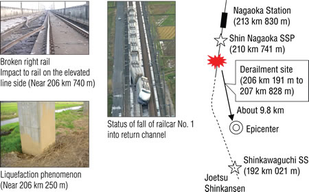
Study and analysis
‹Main study and analysis items›
(1) Damage status of railcars (2) Damage status of track, etc. (3) Damage status of structures (4) Traces of the derailment (5) Component analysis of on-site residues (6) Study of ground near site by boring, and so on - Estimation of derailment stages
(1)
11 axles derailed due to seismic motion
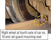
At 17:56:06, the fourth axle of car No. 10 derailed first
↓Subsequently, 4 derailments occurred during large lateral movements in a 4 to 5-second interval
↓11 axles out of 40 axles derailed
(2)
Additionally, 11 axles derailed when the track was broken by derailed wheels
After the fourth derailment, the second, third and fourth axles of the No. 4 car fell to the track
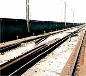
↓Continued running while pushing apart the left and right rails
↓The eight axles of the No. 1 and No. 2 cars then also derailed
↓A total of 11 axles out of 40 axles derailed
(3)
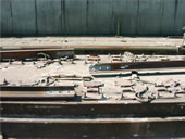
Breakage of the IJ part
The last railcar (No. 1 car) angled into the central return channel because a glued insulated joint (IJ) broke.
(4)
The train was guided by the rails even after derailment and the attitude of the train was maintained until it came to a stop
Since the train traveled along the rails with the rails pinched between the wheels and the bogie parts, the attitude of the train was probably maintained until it came to a stop.
- Effects of subsidence of structure
Subsidence conditions of tracks used in analysis of railcar behavior (high-low displacement of track)
Results of calculation of each axle wheel load of railcar
A part of the bridge pier and viaduct sank because of the earthquake, but we confirmed that this subsidence had a negligible effect on the derailment.
- Simulation of derailment
At the Tokamachi viaduct R3, where the first derailment traces were found, lateral oscillations with a maximum of approximately 700 gal due to seismic motion are estimated to have occurred. Based on the results of rail car motion simulation, it was confirmed that the derailment could have occurred as wheels lifted from the rail.
- Effects of subsidence of structure
Damage to structures and settlement of structures were both negligible, and are not considered to be a cause of the derailment; so the derailment can be considered as having occurred due to seismic motion. Based on the results of the simulations, the mode of derailment can be considered as follows: the railcars oscillated approximately below the center of gravity after receiving large seismic waves resulting in rocking derailment.
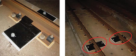
Completion of development
- Railcar guide mechanism to prevent deviation of railcars from rails during derailment (to be introduced from fiscal 2006)
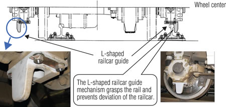
An L-shaped railcar guide mechanism is installed under the axle box of the bogie, and this mechanism prevents the wheels from moving sideways more than a predetermined amount if the car derails.
- Shortening the time required to apply emergency brakes when power to the Shinkansen line is cut off
The system is designed so that when power to the overhead wires is cut off in the Shinkansen lines when an earthquake is detected, the power cut is detected onboard, and the emergency brake is applied to stop the train. A new power detection device was developed that shortens the time from power cut-off in the overhead wires to the application of the brakes.
- Glued insulated joint (IJ) for measures against derailment (to be introduced from 2007)
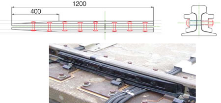
A new glued insulated joint (IJ) was developed that prevents the rail from breaking even when it is subjected to impact from derailed wheels, because of the L-shaped railcar guide.
Measures under development
- Rail anti-toppling devices
A rail anti-toppling device is has two functions: to restrict lateral movement of the rail when lateral pressure acts on the rail from the derailed wheel and railcar guide; and to prevent breakage of the rail when the derailed wheels collide with the rail. Based on the results of investigations to date, a rail anti-toppling device for track slab open sections that can perform these functions is under development.